Neuer Ansatz für ein 200A Powermodul, sehr gut versteckt auf RCGroups

Christian, ein Deutscher, der in Shanghai lebt, hat ein 200A Powermodul Set vorgestellt.
http://www.rcgroups.com/forums/showthread.php?t=2523846
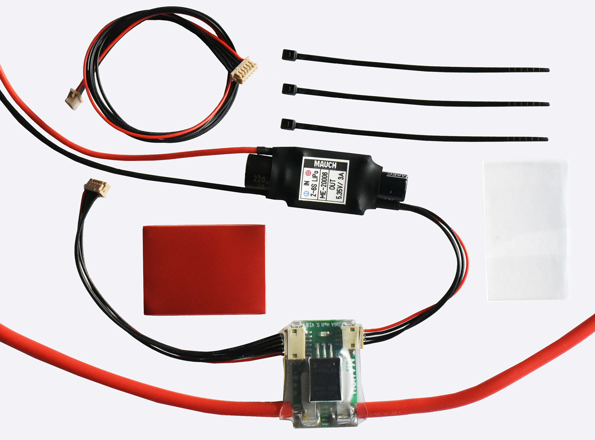
Ein Atto Board mit Hallsensor welches mit (auch für die Versorgung des Attoboards) erforderlichen 5,35V BEC kommt.
Die Serienproduktion hat begonnen:

Es muß nur eins der Akkustecker Kabel getrennt werden. GND braucht man nicht anzufassen.
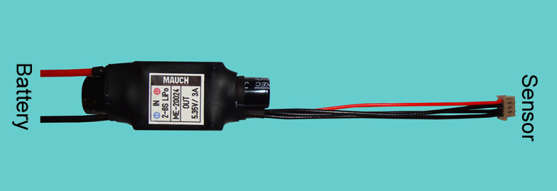
Der BEC entspricht den 3DR Specs bzw. übertrifft diese und kommt in einer Low Ripple Ausführung (0,1%)
Blockschaltbild:
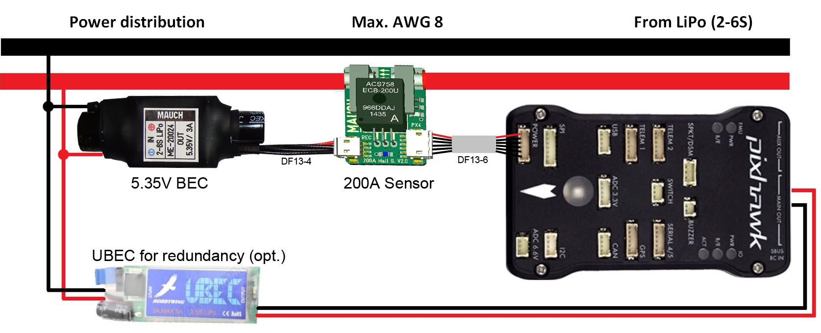
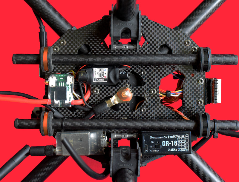
200A Attoboard am PIXHAWK. Hier mit zusätzlichem BEC zur redundanten Versorgung. Natürlich ist das Set auch für APM, AUAV-X2, DroTek und CUAV Pixhack geeignet.
Preis: 33$ inklusive Low Ripple BEC, 2 DF13-6 Kabel Derzeit inklusive Shipping.
Nachtrag 1: FAQ
Nachtrag 2: QC

Christian, ein Deutscher, der in Shanghai lebt, hat ein 200A Powermodul Set vorgestellt.
http://www.rcgroups.com/forums/showthread.php?t=2523846
Ein Atto Board mit Hallsensor welches mit (auch für die Versorgung des Attoboards) erforderlichen 5,35V BEC kommt.
Die Serienproduktion hat begonnen:

Es muß nur eins der Akkustecker Kabel getrennt werden. GND braucht man nicht anzufassen.
Sensor Board:
- Current sensor is a “true hall sensor” up to 200A (ACS758-200U).
- Ultra-low noise power supply (LP2985-4.0) for current sensor and offset shifting circuit.
- Microchip MCP601 operational amplifier for offset shifting.
- LiPo voltage measurement with 1% resistor divider in factor 9:1.
- Supply voltage to Pixhawk / APM = 5.35V/3A
- Bright blue LED as power on indicator.
- 2x10cm / AWG12 cable soldered to current sensor as standard size (Up to AWG8 possible).
- 6 pol cable connection to Pixhawk / APM (both sides DF-13 connector)
- 1x 10cm and 1x 20cm / 6 pole cable in the box to select a different cable length if necessary.
- 18mm x 29mm x 11mm / 7g without cables and shrinking tube.

Der BEC entspricht den 3DR Specs bzw. übertrifft diese und kommt in einer Low Ripple Ausführung (0,1%)
- Input 2-6S LiPo / max. 28V
- Output 5.35V / 3A -> +/- 0.05V –> Ripple 5.5mV (0.1%) at 1.5A output current.
- Input wrong polarity protection, as well as Panasonic FM 220uF/35V input capacitor to prevent burn out of BEC from voltage spikes.
- 4 pole cable to sensor board with DF-13 connector.
- 47mm x 18mm x 11mm / 8g with cables and shrinking tube.

200A Attoboard am PIXHAWK. Hier mit zusätzlichem BEC zur redundanten Versorgung. Natürlich ist das Set auch für APM, AUAV-X2, DroTek und CUAV Pixhack geeignet.
Preis: 33$ inklusive Low Ripple BEC, 2 DF13-6 Kabel Derzeit inklusive Shipping.
Nachtrag 1: FAQ
FAQ:
Why change so fast from V1 to V2 within only a few days ?
- In the beginning the main target was to have a flexible board with just soldering pad’s to connect the cables, but it makes the board a bit bigger in size. Furthermore, some people just don’t have the skills to solder a wire (REM: why somebody in god’s name own an MR if he can’t solder a wire?). So it was decided to install DF-13 connectors with two different cable length, to adjust the distance to the FC (10cm or 20cm). Any other length possible on request and without increasing costs, but might be with a delayed shipping date.
Why Hall sensor:
- The measurement over a normal shunt resistor is not accurate at lower current ( .0A). For a Hall sensor the measurement starts at 0.5A with an accuracy of +/-0.5A over the whole range up to 200A !
- A shunt resistor create heat due to the voltage drop, the hall sensor has only an internal resistance of 100uOhm, so there is no power loss.
- Due to the heat created by a shunt resistor and the power cable, the measurement of the current is not linear and depends on the temperature. This is not happened to a hall sensor, a temperature change (created by the main LiPo cable) will not influence the measurement.
- The current flows only through the hall sensor and NOT through the PCB. Most other current measurement boards has the main cable soldered to the PCB and then it goes to the shunt resistor -> these boards can’t handle over 60A constant current ?
Why only a few supplier use a true hall sensor for current measurement in an MR ?
- Hall sensors are very expensive, compared to a normal shunt resistor and not everybody out there wants to spend the money to top up for a good measurement system. So the sales quantity and profit will not be within the target.
Why output voltage to Pixhawk /APM is 5.35V and not 5.0V ?
- Pixhawk has internally a 3-way power selector over an ideal diode chip. The 3-ways are USB, power connector (6pin) and the Output PWM rail on the back of the FC. So it is possible to power up the FC with either one of this power sources, but how do we know which power source right know is powering up our FC if there is USB, a PM module as well as an backup BEC connected to the output (ESC/Servo) rail ?
The answer is easy: Whichever voltage is higher by 0.25V to any other power source is selected as the internal power supply, as long as this voltage do not exceed 5.70V !
The result in practice on the field can be different, as there are many components connected to the FC like, GPS, Servos, opto ESC’s… etc., the power consumed by the system is not stable, which means the supplied voltage is not stable as well. The reason for this is the loss in voltage due to small power supply cables and maybe many connectors.
To prevent the internal ideal diode to switch too often between different power sources, we choose a bit unusual high voltage (5.35V) as a main power supply. Which means only if any other power supply (USB or PWM rail) is in the small range of 5.35V+0.25V=5.60V and the maximum voltage of 5.70V, then the diode would switch over to the other source.
Why the cable from UBEC to the sensor board is 4 pol ?
- To reduce the resistance in the power line and increase the safety, or should we ask, why does the DF-13 power input of the Pixhawk has +/+/I/U/-/- ?
There are also two wires, for positive and negative, used to reduce the risk of failure.
Why sensor board and UBEC are separated ?
- A switching power supply can be a very “noisy” part in the power supply chain and it is very difficult to shield the coils (1.5MHz) from the current measurement board. So it was decided to keep the two away from each other.
Why is there an additional capacitor installed at the input of the UBEC ?
- Many people complain that the UBEC seems to be bit big, but fact is that he is only 22mm x 17mm. What makes him BIG are the safety capacitors at the input and output !
We all had the issues before that any ESC burned out due to the “hammer effect” in the supply lines, but do we consider that the UBEC is sitting on the same voltage source ?
Does anybody ask himself so far why suddenly his BEC burned out ?
Why does some people add some capacitors onto the ESC’s to reduce the risk of failure, but in the same time they forget that there is also anywhere an BEC in the supply line which might need some protection too ?
How good is it if your ESC’s survive a voltage spike, but your BEC didn’t and the MR crashes ?
If you can answer some of the questions by yourself, then you will also figure out why this UBEC is a bit bigger than others.
Why change so fast from V1 to V2 within only a few days ?
- In the beginning the main target was to have a flexible board with just soldering pad’s to connect the cables, but it makes the board a bit bigger in size. Furthermore, some people just don’t have the skills to solder a wire (REM: why somebody in god’s name own an MR if he can’t solder a wire?). So it was decided to install DF-13 connectors with two different cable length, to adjust the distance to the FC (10cm or 20cm). Any other length possible on request and without increasing costs, but might be with a delayed shipping date.
Why Hall sensor:
- The measurement over a normal shunt resistor is not accurate at lower current (
 .0A). For a Hall sensor the measurement starts at 0.5A with an accuracy of +/-0.5A over the whole range up to 200A !
- A shunt resistor create heat due to the voltage drop, the hall sensor has only an internal resistance of 100uOhm, so there is no power loss.
- Due to the heat created by a shunt resistor and the power cable, the measurement of the current is not linear and depends on the temperature. This is not happened to a hall sensor, a temperature change (created by the main LiPo cable) will not influence the measurement.
- The current flows only through the hall sensor and NOT through the PCB. Most other current measurement boards has the main cable soldered to the PCB and then it goes to the shunt resistor -> these boards can’t handle over 60A constant current ?
Why only a few supplier use a true hall sensor for current measurement in an MR ?
- Hall sensors are very expensive, compared to a normal shunt resistor and not everybody out there wants to spend the money to top up for a good measurement system. So the sales quantity and profit will not be within the target.
Why output voltage to Pixhawk /APM is 5.35V and not 5.0V ?
- Pixhawk has internally a 3-way power selector over an ideal diode chip. The 3-ways are USB, power connector (6pin) and the Output PWM rail on the back of the FC. So it is possible to power up the FC with either one of this power sources, but how do we know which power source right know is powering up our FC if there is USB, a PM module as well as an backup BEC connected to the output (ESC/Servo) rail ?
The answer is easy: Whichever voltage is higher by 0.25V to any other power source is selected as the internal power supply, as long as this voltage do not exceed 5.70V !
The result in practice on the field can be different, as there are many components connected to the FC like, GPS, Servos, opto ESC’s… etc., the power consumed by the system is not stable, which means the supplied voltage is not stable as well. The reason for this is the loss in voltage due to small power supply cables and maybe many connectors.
To prevent the internal ideal diode to switch too often between different power sources, we choose a bit unusual high voltage (5.35V) as a main power supply. Which means only if any other power supply (USB or PWM rail) is in the small range of 5.35V+0.25V=5.60V and the maximum voltage of 5.70V, then the diode would switch over to the other source.
Why the cable from UBEC to the sensor board is 4 pol ?
- To reduce the resistance in the power line and increase the safety, or should we ask, why does the DF-13 power input of the Pixhawk has +/+/I/U/-/- ?
There are also two wires, for positive and negative, used to reduce the risk of failure.
Why sensor board and UBEC are separated ?
- A switching power supply can be a very “noisy” part in the power supply chain and it is very difficult to shield the coils (1.5MHz) from the current measurement board. So it was decided to keep the two away from each other.
Why is there an additional capacitor installed at the input of the UBEC ?
- Many people complain that the UBEC seems to be bit big, but fact is that he is only 22mm x 17mm. What makes him BIG are the safety capacitors at the input and output !
We all had the issues before that any ESC burned out due to the “hammer effect” in the supply lines, but do we consider that the UBEC is sitting on the same voltage source ?
Does anybody ask himself so far why suddenly his BEC burned out ?
Why does some people add some capacitors onto the ESC’s to reduce the risk of failure, but in the same time they forget that there is also anywhere an BEC in the supply line which might need some protection too ?
How good is it if your ESC’s survive a voltage spike, but your BEC didn’t and the MR crashes ?
If you can answer some of the questions by yourself, then you will also figure out why this UBEC is a bit bigger than others.
I got quite some of these questions via PM's and I thought I better post the answers here.
To post here all the quality control during the production would be a very long story, so all I can say is, that it is carried out and recorded.
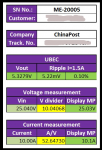
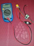
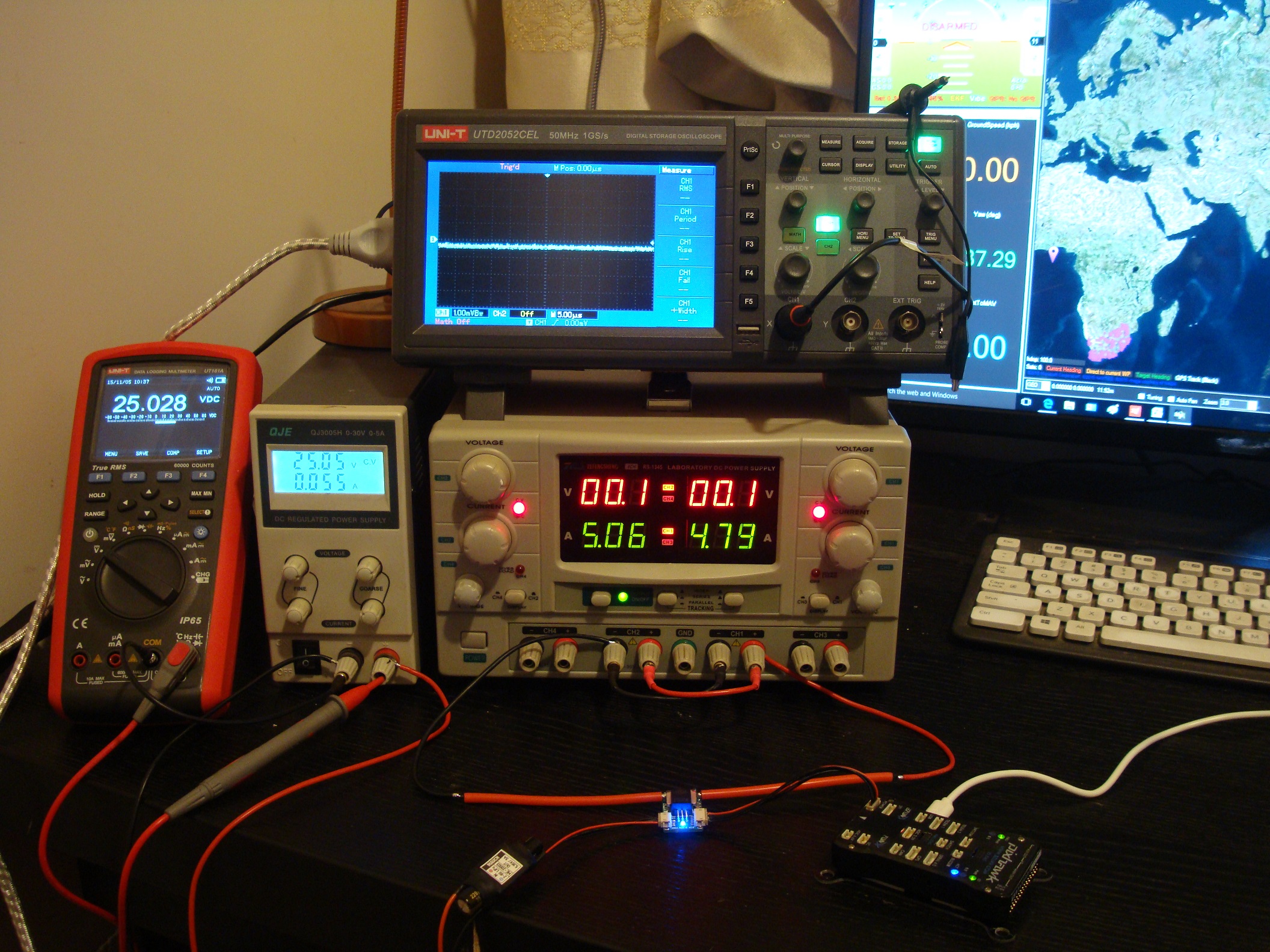
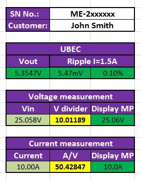
The final QC before the boards are shipped, is a setup with an FC (Pixhawk) and connected to MissionPlanner to check the calibration values for current and voltage measurement.
This final test result will be passed to the customer together with the order confirmation and shipment tracking number by e-mail.
REM: Which power module supplier out there actually use the PM to power up a real FC before shipment ?
So I hope everybody understands, that if I say "safety first"... then I mean it.


Zuletzt bearbeitet:

